Air Fuel Ratio Sensor Wiring Diagram

Vt Commodore Ignition Wiring Diagram, Complete Wiring Diagrams For Holden Commodore VT, VX, VY, VZ, VE, VF, 5.36 MB, 03:54, 32,796, John Amahle, 2018-08-01T19:37:41.000000Z, 19, Vt Commodore Ignition Wiring Diagram, to-ja-to-ty-to-my-to-nasz-swiat.blogspot.com, 1272 x 1800, jpeg, bcm pcm 12j swiat nasz, 20, vt-commodore-ignition-wiring-diagram, Anime Arts
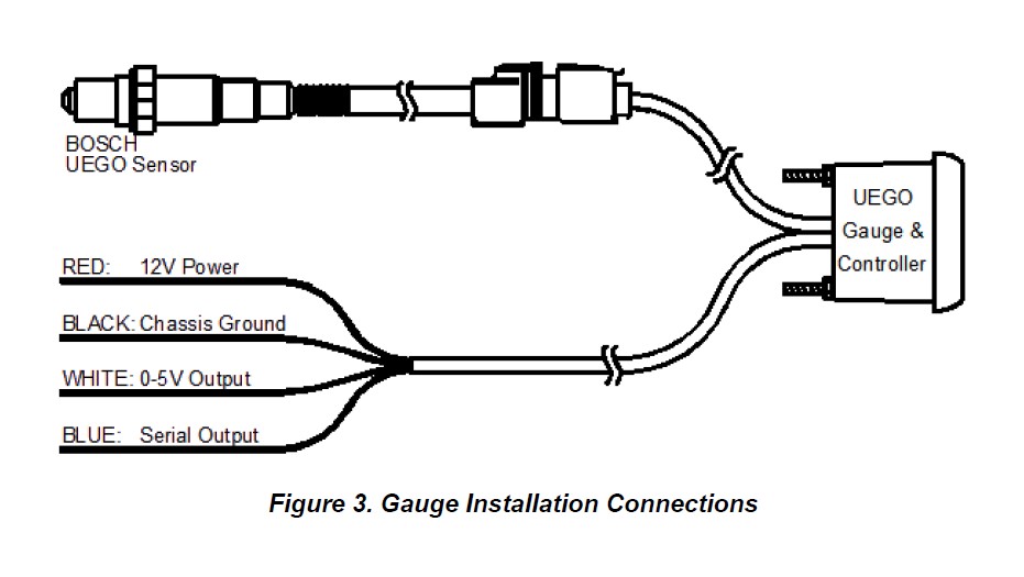
Disconnect vehicle battery before installation. Mount gauge in 52. 4mm diameter hole. Secure with supplied bracket and hardware. Wire gauge as shown in diagram.
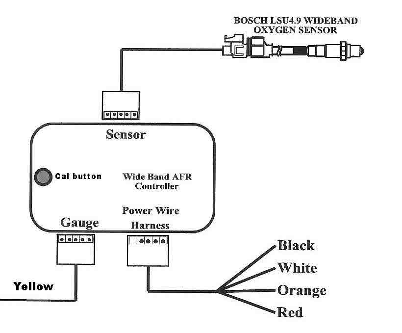
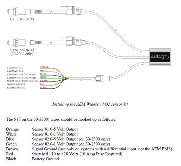
How the sensor responds to changes in the air/fuel ratio. Plug a scan tool into the vehicle diagnostic connector, start the engine and create a momentary change in the air/fuel radio by snapping the throttle or feeding propane into the throttle body. Look for a response from the wideband o2 sensor or a/f sensor. Connect to a fused and switched 12v positive source that is turned on and off with the ignition switch. Connect to good engine ground. Connect to oxygen sensor signal wire. Connect to vehicle wiring harness, not oxygen sensor since some oxygen sensors use shielded wire. Wideband uego air/fuel ratio controller gauges. Bosch 4. 2 lsu wideband sensor with stainless steel tall bung (for 4 channel wb controller).
How to Install an AeroForce Air/Fuel Ratio Sensor Kit on Your 1996-2010 Mustang | AmericanMuscle

Aem Air Fuel Ratio Gauge Wiring Diagram

Aem Air Fuel Gauge Wiring Diagram

Aem Air Fuel Ratio Gauge Wiring Diagram

Plx Wideband Wiring Diagram

Air Fuel Ratio Gauge Wiring Diagram

Installation Instructions for Auto Meter Cobalt Air/Fuel Ratio Gauge - Digital (79-17 All

How to Install AEM Electronics Digital Wideband UEGO Air Fuel Ratio Gauge (97-18 All) on your

