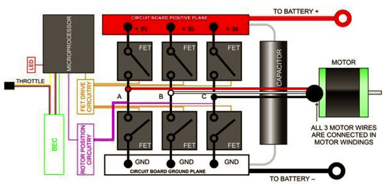
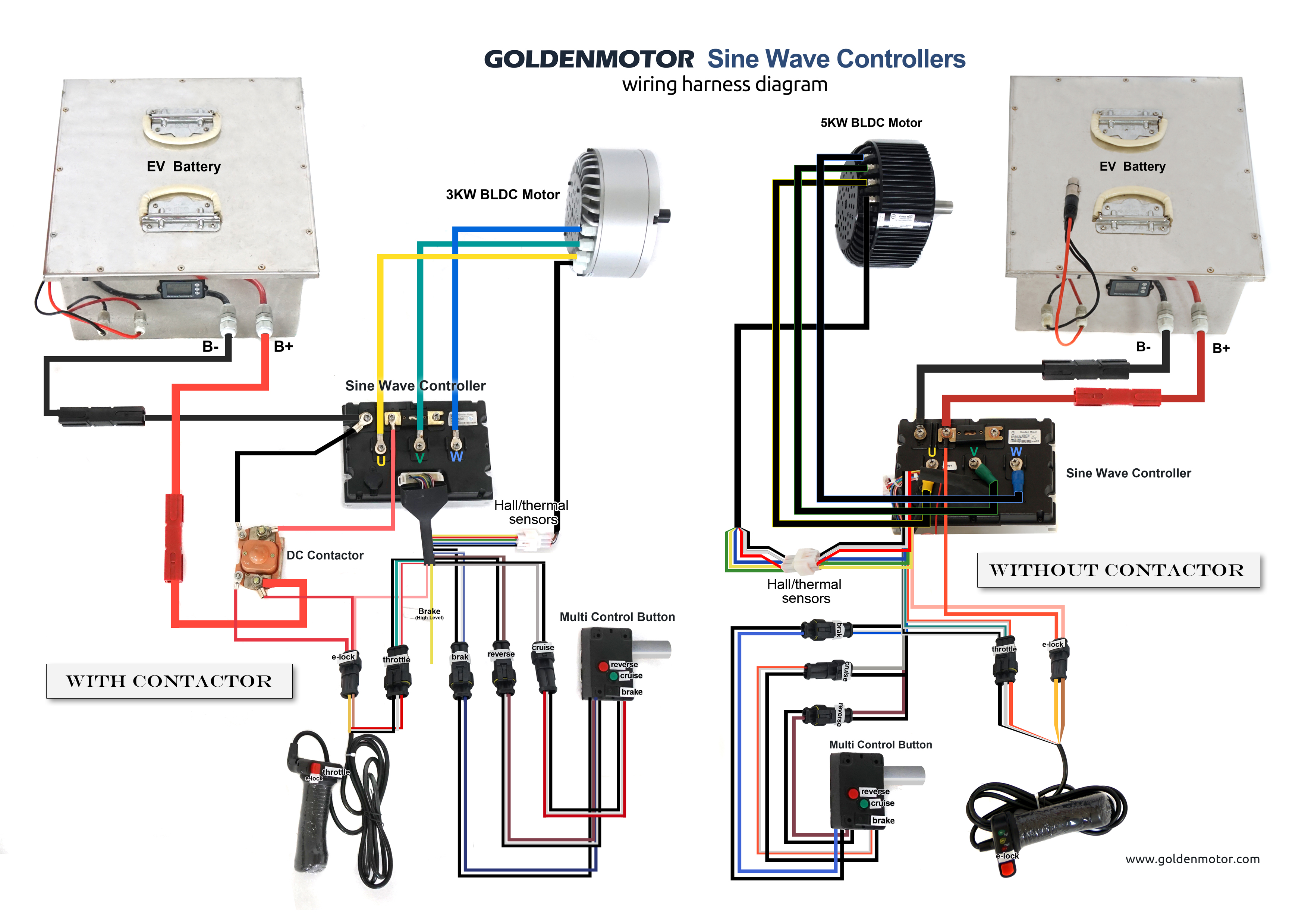
Brushless Rc Motor Wiring Diagram
Vt Commodore Ignition Wiring Diagram, Complete Wiring Diagrams For Holden Commodore VT, VX, VY, VZ, VE, VF, 5.36 MB, 03:54, 32,796, John Amahle, 2018-08-01T19:37:41.000000Z, 19, Vt Commodore Ignition Wiring Diagram, to-ja-to-ty-to-my-to-nasz-swiat.blogspot.com, 1272 x 1800, jpeg, bcm pcm 12j swiat nasz, 20, vt-commodore-ignition-wiring-diagram, Anime Arts
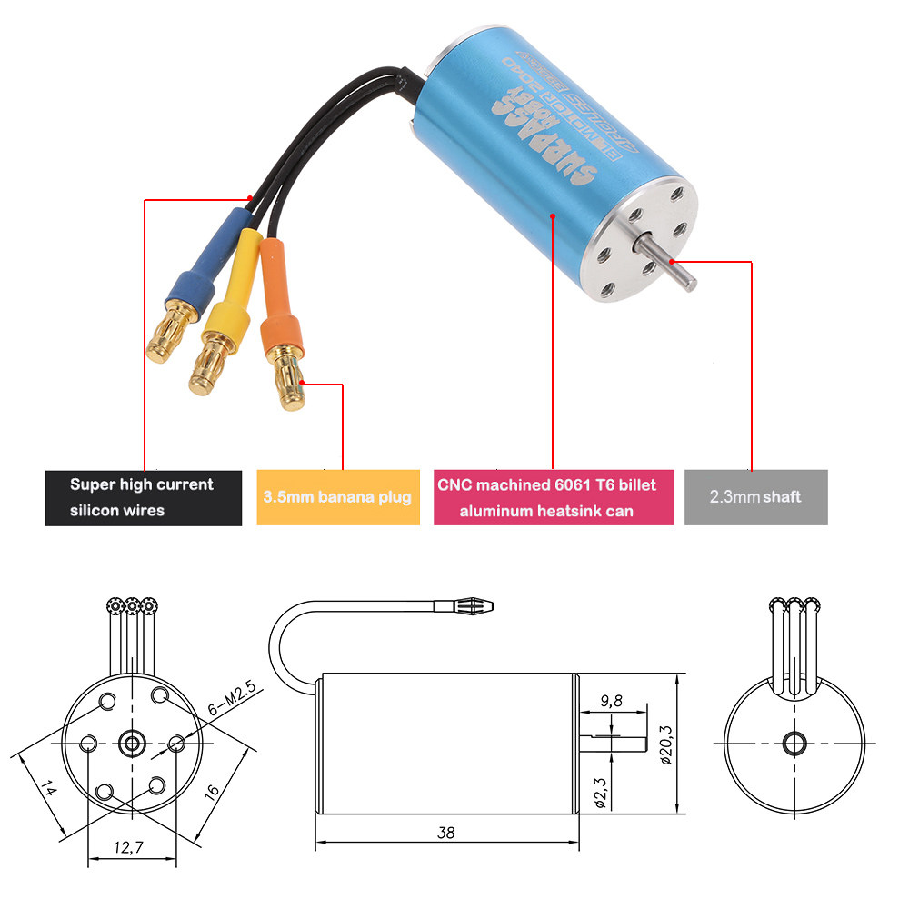
Add wire insulation to copper wire. Here i used insulation sleeve of multicore wire to insulate them as shown in a picture. Add bullet connector to motor terminals as shown in a picture. Add heat shrink tube coating for extra strength and insulation.
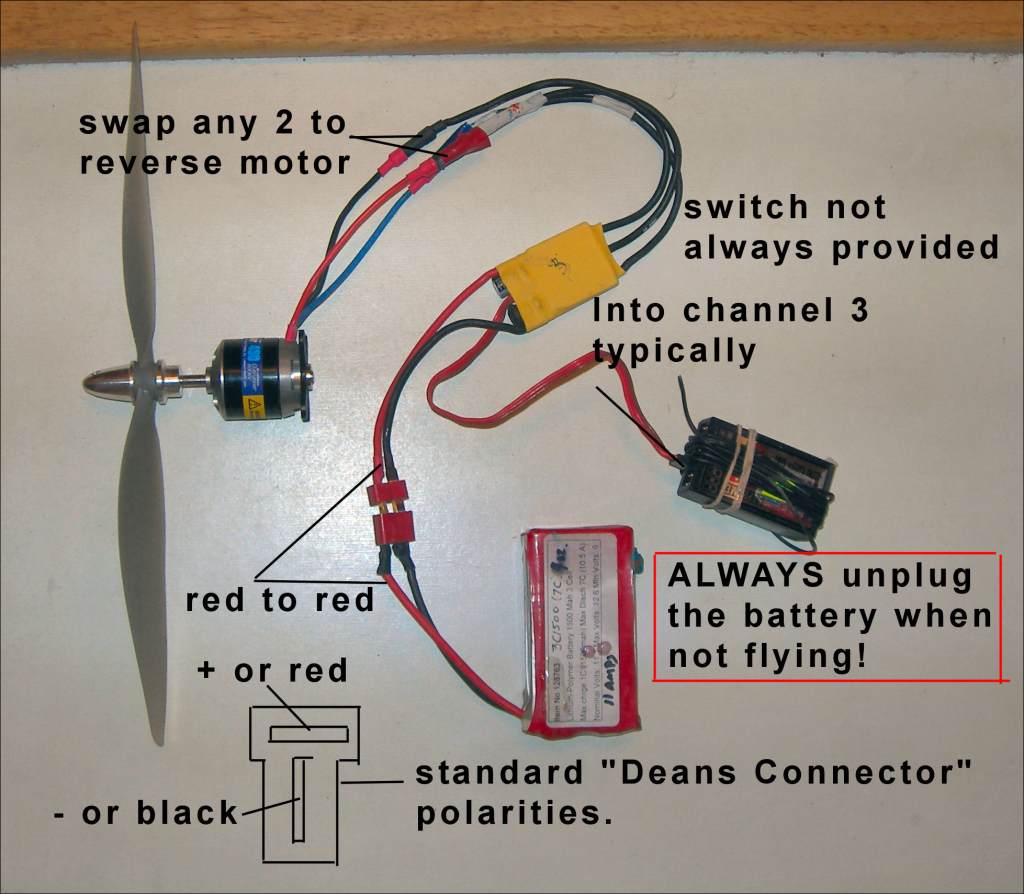
1) connect all components with exception of motor and battery. 2) double check you have everything connected as shown in diagram. 3) power on your tx (transmitter/radio) 4) connect the battery. . if the servos respond to tx stick movements, your system is functioning properly. You can now safely connect the motor. Below is a diagram to show how to wire a typical brushless motor system. Select from the options below to show the appropriate wiring diagram depending on your particular setup. Cable av usb gopro fpv hero diagram wiring power pro input wire plug ready views voltage 5v gothelirc. Rc helicopter 40a esc brushless motor speed controllers.
Attachment browser: BrushlessMotorLayout.jpg by Sparky Paul - RC Groups

how do you connect 2 brushless motors - Page 2 - RC Groups
Rc Brushless Motor Wiring Diagram - Wiring23
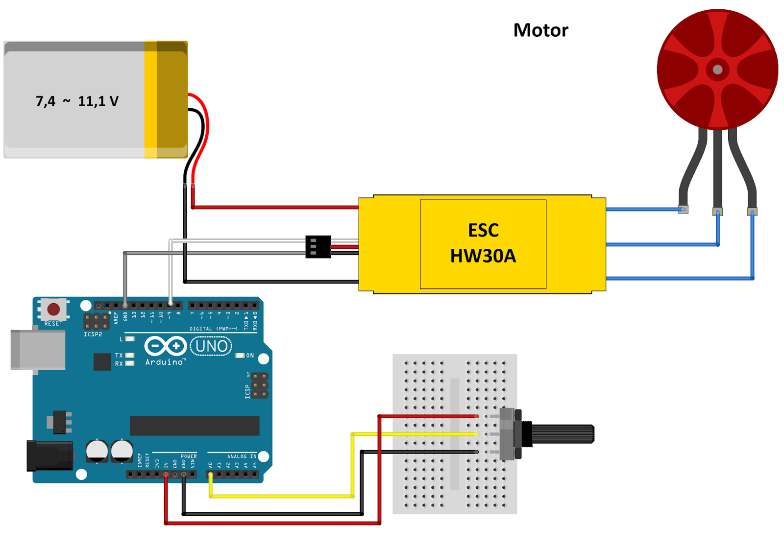
dual brushless setup

Brushless Motor Wire Diagram - Wiring Diagram Schemas
Brushless Motor Controller Wiring Diagram - Wiring Diagram
how do you connect 2 brushless motors - Page 2 - RC Groups
theLEDwheel: December 2015

Using a Brushless DC motor with an RC ESC | Mbed
